The windscreen was installed professionally. I just had to do the electronics and after help from lr4x4 and especially this post this is what I have achieved.
Here is the circuit I have gone for.
I could have used the conventional landrover circuit but I find switching earth very confusing.
Why do you need a timer relay & a high current relay?
- This is because the windscreen takes 30Amps and a timer relay is only designed for about 10Amps and the switch for less than that.
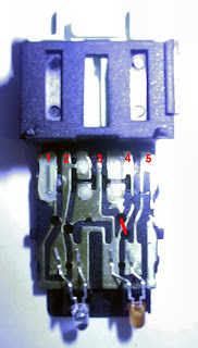
Before the modification the terminals are :
Pin 1 - from Timer Relay
Pin 2 - Live from Dash Illumination
Pin 3 - Not Used (but internally connected to Pin 4)
Pin 4 - To Earth
Pin 5 - Live from output side of Relay (to light the tell-tale LED)
Pin 2 - Live from Dash Illumination
Pin 3 - Not Used (but internally connected to Pin 4)
Pin 4 - To Earth
Pin 5 - Live from output side of Relay (to light the tell-tale LED)
Opening the switch is a little tricky. There are some catches which can be pushed in with a very fine screw driver and the switch pings in half if you push it apart with your thumbs.
After the modification the terminals are:
Pin 1 - Live from fusebox
Pin 2 - Live from Dash Illumination
Pin 3 - To Earth
Pin 4 - Switched Live Pulse to VWP relay
Pin 5 - Live from output side of Relay (to light the tell-tale LED)
To wire up the switch you need a connector plug. These are hard to come by & the only supplier I could find was a ZZPLUG01 from Dingocraft. This needed a small amount of surgery with a stanley knife so perhaps I should have got the ZZPLUG02, but it is in and works.
The connections for the timer relay are:
Terminal 1 - A momentary 12V from
your switch, this starts the timed session
Terminal 2 - Earth
Terminal 3 - Fused 12V supply from battery, this is where your screen gets it power from.
Terminal 4 - Ignition 12V. This is what makes the internals of your timer work
Terminal 5 - Goes to positive terminal of your screen.
Terminal 2 - Earth
Terminal 3 - Fused 12V supply from battery, this is where your screen gets it power from.
Terminal 4 - Ignition 12V. This is what makes the internals of your timer work
Terminal 5 - Goes to positive terminal of your screen.
The correct way to get the power to the switch & timer relay is to use a feed from the oil pressure switch but I have to confess I did not know where that was. The reason for using the oil pressure switch is to stop you using the windscreen without the engine running (to stop you getting a flat battery).
I cheated. The electric windows will only work with the ignition fully on so I took my feed from there, with the addition of a 5Amp fuse between the electric window feed and my circuits. It is obviously possible to turn the ignition to position 3 and not start the vehicle & then turn on the windscreen but who would be so daft.....Only time will tell!
Next up I will be fitting heated mirrors from mudstuff. The circuitry will be identical except that they do not need a feed direct from the battery as they only draw a couple of amps.
Significant Parts list:
dash switch - part number: YUG000460LNF
timer relay - part number: Ref:74350
high current relay: maxi relay Ref: 268763
dash switch connector

