Showing posts with label defender. Show all posts

Monday, 14 January 2013

defender TD5 starter motor removal

Three times in the last month my defender has failed to start.
Turns out it was the starter motor and a judicious tap with a hammer on the motor would spring it back to life.

Now this is obviously not a permanent fix and sooner or later it would fail permanently.

New starter motors can be £200+ & then there is the garage charges making this a costly failure.
A few google searches and the most likely issue is the solenoid contacts so I purchased a kit from repairkitsuk. I paid the extra and got the kit next day.

The starter motor is a tad awkward to get at to say the least & an assistant will make life a lot easier.

To remove the motor you will need a
  •  13mm socket
  • 15mm socket
  • 3 inch extension
  • universal joint
  • 3 ten inch extenders
  • possibly 13 & 15mm spanners
  • 1/2 inch drive
To open up the solenoid you will need:

  • 12 or 14mm spanner - can't remember
  • 8mm socket

The starter motor is held on with two 13mm bolts & a 15mm nut, The two 13mm nuts are relatively easy to see & get at from underneath. The tricky one is the 15mm nut. This is located on the inside side of the starter at the top & there is not enough room to get a socket & ratchet in from the top.
  1. Disconnect the battery 
  2. First off remove the top engine cover. Not absolutely necessary but it lets a lot more light in
  3. Disconnect the bottom pan & shove to the LHS.
  4. Disconnect the electrical connections
  5.  Loosen the two 13mm nuts - access from underneath.
  6. 15mm nut
    1. attach the 15mm socket, 3 inch extension & universal
    2. get the assistant to attach this to the nut accessing the starter from above & stay there waiting...
    3. Connect the three 10 inch extensions to the drive
    4. NB access is not from fully underneath
    5. Insert the extension set from the front above the floor pan & differential at an angle of about 30 degrees upwards. You might see the assistants fingers.
    6. The assistant can then get the extension to connect in to the universal
    7. Undo the 15 mm nut
  7. Remove the two 13mm nuts
  8. The starter motor is now free to remove.

The instructions provided by repairkitsuk were perfect. We actually only changed the plunger & contacts. Other parts are provided but we decided everything was good.

Assembly is simply the reverse process.

Wednesday, 30 November 2011

Heated Windscreen for a Landrover Defender

I bought myself a landrover Defender just before last winter & after having to scrape ice off the inside as well as the outside I thought I would invest in a heated windscreen.

The windscreen was installed professionally. I just had to do the electronics and after help from lr4x4 and especially this post this is what I have achieved.

Here is the circuit I have gone for.


I could have used the conventional landrover circuit but I find switching earth very confusing.

Why do you need a timer relay & a high current relay?
  •  This is because the windscreen takes 30Amps and a timer relay is only designed for about 10Amps and the switch for less than that.
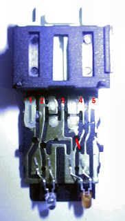
A simple switch from maplin would suffice but I fancied a proper landrover switch. The slight issue here is that the switch is designed to switch earth. Thankfully a clever gent from lr4x4 has suggested this mod and I can vouch that it works. You need to open up the switch carefully and cut one of the tracks.

Before the modification the terminals are :

     Pin 1 - from Timer Relay
     Pin 2 - Live from Dash Illumination
     Pin 3 - Not Used (but internally connected to Pin 4)
     Pin 4 - To Earth
    Pin 5 - Live from output side of Relay (to light the tell-tale LED)


Opening the switch is a little tricky. There are some catches which can be pushed in with a very fine screw driver and the switch pings in half if you push it apart with your thumbs.

After the modification the terminals are:

     Pin 1 - Live from fusebox
     Pin 2 - Live from Dash Illumination
    Pin 3 - To Earth
    Pin 4 - Switched Live Pulse to VWP relay
    Pin 5 - Live from output side of Relay (to light the tell-tale LED)


To wire up the switch you need a connector plug. These are hard to come by & the only supplier I could find was a ZZPLUG01 from Dingocraft. This needed a small amount of surgery with a stanley knife so perhaps I should have got the ZZPLUG02, but it is in and works.

The connections for the timer relay are:
     Terminal 1 - A momentary 12V from your switch, this starts the timed session
     Terminal 2 - Earth
     Terminal 3 - Fused 12V supply from battery, this is where your screen gets it power from.
     Terminal 4 - Ignition 12V. This is what makes the internals of your timer work
     Terminal 5 - Goes to positive terminal of your screen. 


The correct way to get the power to the switch & timer relay is to use a feed from the oil pressure switch but I have to confess I did not know where that was. The reason for using the oil pressure switch is to stop you using the windscreen without the engine running (to stop you getting a flat battery).

I cheated. The electric windows will only work with the ignition fully on so I took my feed from there, with the addition of a 5Amp fuse between the electric window feed and my circuits. It is obviously possible to turn the ignition to position 3 and not start the vehicle & then turn on the windscreen but who would be so daft.....Only time will tell!

Next up I will be fitting heated mirrors from mudstuff. The circuitry will be identical except that they do not need a feed direct from the battery as they only draw a couple of amps.

Significant Parts list:
    dash switch - part number: YUG000460LNF
    timer relay - part number: Ref:74350
    high current relay: maxi relay Ref: 268763
    dash switch connector